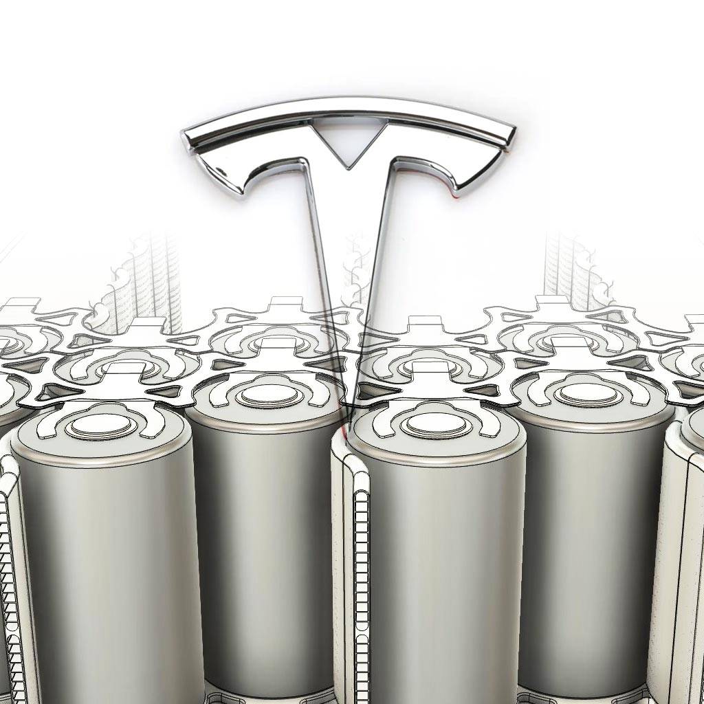
Tesla’s innovative 4680 battery cell has garnered significant attention in the automotive and energy sectors, marking a transformative leap in battery technology. This article delves into the intricacies of Tesla’s approach to the large circular PACK design, exploring the specifications, advantages, and implications for future electric vehicles (EVs).

Understanding the 4680 Battery Cell
The 4680 battery cell, named for its dimensions—46 mm in diameter and 80 mm in height—represents a new era in cylindrical battery design. This cell format is designed to enhance energy density and reduce manufacturing complexity while increasing overall performance.
Key Specifications
- Weight: Approximately 355 grams per cell.
- Capacity: Estimated at 26.136 Ah, translating to an energy output of 96-99 Wh at nominal voltages of 3.7-3.8 V.
- Energy Density: Ranges from 272 to 296 Wh/kg, making it competitive with existing technologies.
The 4680 cells utilize a tabless design, which simplifies assembly and reduces internal resistance, ultimately leading to improved performance during charge and discharge cycles.
Advantages of the 4680 Design
1. Increased Energy Density
The 4680 cells are engineered to store more energy than their predecessors. Compared to the smaller 2170 cells, the 4680 cells can store over five times more energy, significantly enhancing the range of Tesla vehicles.
2. Structural Battery Pack Design
One of the most innovative aspects of the 4680 cell is its role in creating a structural battery pack. The thicker steel casing (500-600 μm) provides additional strength, allowing the battery pack itself to contribute to the vehicle’s structural integrity. This design reduces overall vehicle weight while improving safety.
3. Simplified Manufacturing Process
The tabless design not only enhances performance but also streamlines production. Fewer components mean reduced manufacturing costs and time, which is crucial for scaling production to meet growing demand.

Comparative Analysis: 4680 vs. 2170 Cells
| Feature | 4680 Battery Cell | 2170 Battery Cell |
|---|---|---|
| Diameter | 46 mm | 21 mm |
| Height | 80 mm | 70 mm |
| Weight | 355 g | Approximately 250 g |
| Energy Density | 272-296 Wh/kg | 263-276 Wh/kg |
| Capacity | Up to 26.136 Ah | Up to 5 Ah |
The transition from the 2170 format to the larger 4680 design allows for fewer cells per pack, reducing complexity and improving efficiency in both assembly and thermal management.
The Impact on Electric Vehicles
1. Enhanced Range and Performance
With higher energy densities, Tesla’s vehicles equipped with the 4680 cells can achieve greater ranges without increasing battery size or weight. For instance, early models utilizing these cells are projected to offer a range of approximately 279 miles, despite having a smaller total kWh capacity compared to previous models.
2. Cost Reduction
The simplified manufacturing process associated with the 4680 cells is expected to drive down costs significantly. By reducing the number of components required for each battery pack, Tesla aims to lower overall production expenses, which could translate into more affordable EV options for consumers.
3. Sustainability Considerations
Tesla’s commitment to sustainability is reflected in its battery technology advancements. The use of abundant materials like aluminum reduces reliance on scarce resources such as lithium, aligning with broader environmental goals.
Future Developments: Gen 2 and Beyond
Tesla is not resting on its laurels with the initial release of the 4680 cells. The upcoming Gen 2 version, referred to as the “Cybercell,” promises further enhancements:
- Weight Reduction: The shell weight has been optimized from 70g down to just 49g, contributing to an overall lighter battery pack.
- Increased Energy Density: Early estimates suggest that Gen 2 cells may achieve a further increase in energy density by approximately 10%, enhancing overall vehicle performance.
These advancements position Tesla at the forefront of battery technology innovation, ensuring that it remains competitive in an increasingly crowded EV market.
Challenges Ahead
Despite the promising features of the 4680 battery cell, challenges remain:
1. Production Scalability
Scaling up production to meet global demand while maintaining quality standards will be critical for Tesla’s success with the 4680 technology.
2. Market Competition
As other manufacturers invest heavily in battery technology, Tesla will need to continuously innovate to maintain its lead in performance and cost-effectiveness.
Conclusion
Tesla’s approach to large circular PACK design through its innovative 4680 battery cells marks a significant advancement in electric vehicle technology. With enhanced energy density, structural integrity, and simplified manufacturing processes, these cells are poised to redefine what is possible in sustainable transportation.As we look towards a future increasingly dominated by electric vehicles, Tesla’s commitment to innovation and sustainability positions it as a leader in shaping this new landscape. The ongoing developments within the realm of battery technology will undoubtedly play a pivotal role in driving widespread adoption of electric vehicles globally.